첨부이미지
(첨부가 프로그램에 이상이있는지 안되더라구요..ㅠㅠ 하는수없이 링크로..)
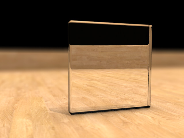
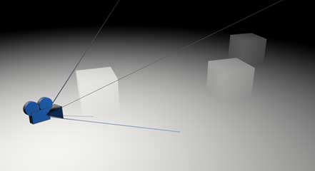
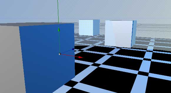
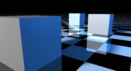
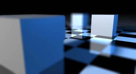
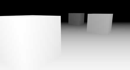
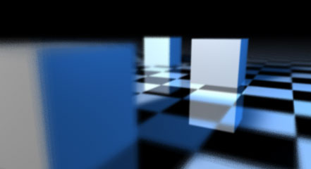
투명한 물체안에 보이는 뒷쪽 배경은 심도의 영향을 적용받지 못하고있습니다...
이와 비슷한 것으로는 알파값을 줬을경우.. 나머지 보이지 않는 부분에 비치는 뒷배경은
피사계 심도의 영향을 받지 못하는데요.. 이문제.... 해결할 방법은 없을까요...?????
.gif)
True Depth of Field | ||||||||||||||
The Depth of Field effect in cinema 4d has been rather puny to say the least up until Version 8, but now we have depth of field that's actually noticeable on an image larger than a postage stamp "Hurrah!" I hear you say. Well, don't get too excited, there are a number of problems with this ne DOF filter "Boo!" but don't despair. I'm here to help you with a rather neat workaround that should with careful work give you the results you dream of.
Simply put the DOF effect in C4D is in fact a post effect which uses what's known as the Z-Buffer to determine blurriness. Ok so firstly you might want to know what a Z-Buffer is In 3D space there are three directions, left/right, up/down and forwards/backwards. These are shortened to their mathematical names X,Y and Z. A Z-Buffer is a representation of the distance objects are away from you the viewer. Here's one of our scene:
All the DOF effect does is take this information and depending on the value at that point in the Z-Buffer it blurs by a set amount. Think of it like an alpha channel for blurring in this case. Everything Mid gray in our image will be left intact, but to either side it will get progressively more blurry, of course if the focal point was nearer then C4D would know to change the range of values that get blurred and those that don't. Now here's where our problems come in though, due to the nature of using this method things that are transparent and things that are reflective get blurred only by the value of their surface in the Z-Buffer, for instance if you look a the floor in the Z-buffer image you'll notice that it's a uniform gray gradient all the way up. This means that any color on that surface, even if it's a reflection will get blurred if it's not in the mid-tone section, and any reflection that's in the mid-tone section (our distant cubes reflection) will remain sharply in focus because this is a pixel filter(it takes the value of the pixel and it's neighbors and calculates the result from that), very much like the filters in Photoshop. This isn't true depth of field. However I figured that with a little ingenuity you could create the true effect using motion blur to your advantage, by simply shaking the camera around while keeping it focused on a point you should get true DOF, so how do we do this? How to make True Depth of Field in Cinema 4D 8 (this can be done using Blunt Trauma in C4D Version 7.3) I used the following objects and hierarchy in my scene to control my camera for this.
6) Group all of this and call it "Focus Blur Camera" for easy reference. Add a User Data field in the Attributes manage for this object and make it a "Real" % with no maximum value, make it's name "Blur Amount". Don't ever move this object, instead always move the "camera holder" object and the "Camera.Target" to track around the scene. So what are we going to do here? When I said we wanted to move the camera around it's no good for us to move the camera around completely randomly. This is because if you do you'll end up with flickering frames. What we want is a nice controlled set of samples. The easiest way to do this is to rotate the camera around a point, that's why we've grouped the camera under a null. However if we were to simply rotate the "camera holder" null the camera would rotate also which wouldn't be desirable. Now the simplest way to deal with that would be to rotate the camera in the opposite direction, however that would firstly make animating the camera difficult, and secondly would spoil the fun of learning a little Xpresso. So here's what we're going to do. Instead of rotating the camera, or it's null, or putting it under another null and rotating that, we're going to rotate the camera pivot object, have the blur object slightly offset from the camera pivot object to give us our wobble, and we'll take the blur objects position relative to the camera pivot and translate that directly onto our camera objects position relative to the camera holder object. This means that we shouldn't move the camera pivot object or the blur object from the zero axis, nor should we move the camera object directly, but we can move the camera holder object, and the camera target object. Now you'll notice on the Camera Pivot object is an xpresso expression, and here it is in all it's glory. Yikes! Ok take a moment to scan through this and the remarks I've put down on it. Now this isn't as scary as it looks, and it will help you a lot. The most complex part is the bit in the middle, the RangeMapper node which makes the blur object move in and out so's not to have just a purely circular motion (as that wouldn't give as good blur effect). So let's build this up. Firstly of course you're going to need to add a new Xpresso expression to your camera pivot object, do so and in the new window that opens up right click to choose New Node->Xpresso->General->Time. Make sure this node has the following outputs "Real" and "Frames per second", we're going to multiply the time by the frames per second to get the frames in whole numbers because if we were to use "Frames" as an output it would only update the movement at each frame, seeing as we're using Motion blur to achieve our effect it's important that we have a smooth motion even between frames. Next add a Math (Right click New Node->Xpresso->Calculate->Math) connect "Real" and "Frames per Second" to the two inputs on the Math node, then click on the left hand blue box on the math node and select "Input" to add a new input. Now you'll notice that it's actually set to add, so with the Math node selected go to the attributes manager and change the function to "Multiply", and in the input field there type in "2*pi", Cinema 4D knows that value of PI and will substitute that for you, we need to use that value as angles within Xpresso tend to be in radians (where a whole rotation is two times that mathematical value PI). Add another Math node, make it into a multiply node and set the second input value to 7. Then connect the output of the first math node to the first input on this math node. We're multiplying by seven because it creates a nice range of samples by rotating the camera pivot object seven times while the blur object moves out, this way it wont be blurry on one side, but not on the other( due to a spiral like set of samples. Now drag and drop that camera pivot object from the object list (click and drag the icon) onto the Xpresso workspace. From the inputs select Position->Global Rotation->Global Rotation.B. Then connect this to the output of our second Math node. Now the camera pivot object will rotate 360 degrees each and every frame, regardless of what the frame rate of our document is.
Now add another Math node, make it a math Multiply, and add another input to it. Connect the output of the RangeMapper node to the first input. This node will be the one that multiplies all the factors that determine how much blur there is and turns that into a value for the position of the blur null object. To get the Blur amount value that we created as a User Value on the Focus Blur Camera Null you have to first drag the Focus Blur Camera null onto the the Xpresso workspace (from the object manager list) and then select from the outputs User Value->Blur Amount. It's as simple as that. Because as it currently stands any blur above 10% would be way too much and even at 10% it's a lot we'll divide this value to make it smaller before inputting it into our mixing math multiply node. Add another Math node, make it into a divide node, and I suggest putting in a value of 30 into the second input. Connect the output "Blur Amount" from the Focus Blur Camera object to the first input. Then connect the output to the second input of out mixing math node we create a couple of steps back. Next we need to calculate the distance the camera is from the target, two reasons. Firstly we don't want the camera moving about as much if the camera is close to the target, otherwise it would never work, second reason is we want to make life easier for ourselves and I've developed many ways of making my life easier, one of those secrets i'll let you into right now. When i need to work on a scene that involves depth of field the camera object has no gizmo to really show exactly what will be in focus and what wont. So what i do is i attach a sphere to the camera and then set the radius equal to the focal point distance. This shows me exactly what will be in focus and what wont, and that's what we're doing here, that's what the "focus area" object we added at the beginning is here for. So to work out the distance between these two objects we drag them onto the Xpresso workspace first off, we'll use the camera holder object rather than the Camera object simply because we don't want this value to change as the camera "shakes". For all intents and purposes the camera holder object is now our camera object when animating. Then we drag the Camera.Target object onto the Xpresso workspace. For both objects make their Global Position output visible. Then make a new node, again under calculate, this one is called Distance, and it does exactly that. Connect the outputs of our two objects to the inputs of the distance node, and then connect the output of the distance node to the last free input of out math multiply mixer node. Then in order to control the size of our sphere so that it shows us the focus plane, drag the focus area object onto the Xpresso workspace, and from the inputs on it select Basic Properties->Radius. Then connect the output of the distance node to the input of the focus area node. Now you will be able to see what is in focus by seeing what that sphere intersects. Always make sure that the sphere is centered on the camera holder object (it's local/object position should be 0,0,0 in the Co-ordinates manager).
We're nearly there now, the math multiply mixer node is all ready to output, but first we have to convert it's output which is a real into a vector for input into the blur objects x position. We wont change the math nodes type to vector instead we'll use an Adapter node. So make a new Real2Vector node (you'll find this under right click New Node->Xpresso->Adapter->Reals2Vector). Connect the output of our Math multiply node to the X input of the Reals2Vector node. Next drag the blur object onto the Xpresso workspace to create a new object node and make the Position.X input visible, then connect the output of the Reals2Vector node to this input. Now the blur object will move in and out from the camera pivot object over the course of a single frame by the amount specified in blur amount multiplied by the distance that the camera is from the target ;). To finish this network off we need to connect the global position of the blur object (which is its position in the overall workspace) to the position of the camera object (which is it's position relative to it's parent object camera holder). This is simply done by dragging the camera object onto the Xpresso workspace and then making the Global Position output visible on the blur object node, and making the Position input visible on the Camera node, then connecting the two. Congratulations you've just finished the Xpresso part of this. Now to put in the finishing touches before we render. For motion blur to work you will have to of course switch it on. You will need to switch on Scene Motion blur in the effects part of the render settings dialog box, set the number of Samples to 25, you want it to be as smooth as possible, also bring up the dither if you want.If you want you can soften the blur a little more by using filters like Softem, or Median. I suggest switching Antialiasing off to speed things up quite a lot, don't worry due to the nature of taking so many samples you should still end up with a nice aliased image. Next you should set a value for the amount of blur using the User Value on the Focus Blur Object. Just do this by selecting the focus blur object and under the User Value tab in the Attributes manager change the percentage to whatever you like. I suggest 50% as a good starting point. Then position your Camera by moving the camera holder object, and the Camera.Target object into place. Once you render you should get a result not unlike this one. Notice the true reflections? Lets compare it with the Z-Buffer DOF Moving the camera produces a much better (truer) result. Of course this method will work with transparency too which is an added bonus, but it's render times can be quite high as a result of the way it has to render out 25 frames compared to the single frame with Z-Buffer DOF. Also it's smoothness is limited by the number of samples that scene motion blur takes in C4D8, so the smoothest it will get is with scene motion blur at 25 samples with dither. And here are the scene files (for C4D 8 only) |